Just Constructed A Power Supply Box For My In-process Led Build.
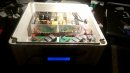
Nothing too fancy. Just a pair of 250W (48VDC/5A output) open rail supplies, a pair of XLR sockets, a fused and switched IEC inlet, and a metal enclosure.

The 240VAC in has a 6.3A fast blow ceramic fuse in it. Each power supply draws a maximum of 2.5A. A pair of them in parallel draws a maximum of 5A. The next closest fuse value is 6.3A (using a 5A fuse wouldn't work as it would be constantly popping). So basically if the worst happens and a short forms, as soon as the current exceeds 6.3A (which it should quickly) the fuse will pop and cut power.

From the back of the connectors you can see that I've used large, solid crimp connectors for the spade terminals (except the live/neutral feeds to the switch, they weren't needed - live and neutral OFF the switch to the supplies use spades also) and heatshrink protected solder connections for the DC output.

Power supply rails. As you can see, I've used open spades with extremely solid crimps and soldered the wires as well for additional bond strength. Once the screws are tightened down on these, they don't move.
All cables were tested at both ends with a multimeter to make sure connections were good and there were no shorts. Input and output voltage were measured and were exactly where they needed to be and were completely stable. Input current was measured and was actually drawing LESS than expected, probably because there was no load on the supplies. I'm going to get a sparky friend to check over my work for safety's sake of course.
The 240VAC in has a 6.3A fast blow ceramic fuse in it. Each power supply draws a maximum of 2.5A. A pair of them in parallel draws a maximum of 5A. The next closest fuse value is 6.3A (using a 5A fuse wouldn't work as it would be constantly popping). So basically if the worst happens and a short forms, as soon as the current exceeds 6.3A (which it should quickly) the fuse will pop and cut power.
From the back of the connectors you can see that I've used large, solid crimp connectors for the spade terminals (except the live/neutral feeds to the switch, they weren't needed - live and neutral OFF the switch to the supplies use spades also) and heatshrink protected solder connections for the DC output.
Power supply rails. As you can see, I've used open spades with extremely solid crimps and soldered the wires as well for additional bond strength. Once the screws are tightened down on these, they don't move.
All cables were tested at both ends with a multimeter to make sure connections were good and there were no shorts. Input and output voltage were measured and were exactly where they needed to be and were completely stable. Input current was measured and was actually drawing LESS than expected, probably because there was no load on the supplies. I'm going to get a sparky friend to check over my work for safety's sake of course.