@deediro - Ken has some of the boards already soldered up - including IC sockets and screw terminals :)

Reef Discussion
Sorry @deediro, I had to drive home. Send me a message if you need to pick some up. :)
@Synodontis Can I grab 3 off you on Saturday Ken?
Hi @daveH I know you wrote this about 3 months ago, but I didn't see an answer to your question re: a physical switch to turn off the LDDS.How's everyone progressing with the new drivers? Anyone got them up and fully running?
I decided to add some exotics to my setup seeing as it was easy now to add further LED strings with the new driver and thanks to @MagicJ's neat board.
My new LEDs have arrived so I'll be doing some Easter soldering/wiring.
I mentioned before about wanting to be able to 'switch' off/on each string so that I can see them individually for their effect.
I've worked out that I'll have a series of buttons that will work from the arduino sketch that will do the individual on/off functions. Hopefully that will work OK.
Has anyone tried to turn the individual strings on/off?
I'm hoping the previous sketch for dimming will be workable for the new setup also. Has anyone written a sketch that works for the new drivers?
I am in the middle of building a light for a nano and have had a pretty good look at the circuits involved and the LDDs
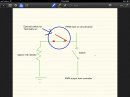
@MagicJ may have some input here, but as I see it there may be one issue with the LDDs depending on the strength of your lighting and the way you control it in the case of power failure. If you lose power to the controller then the lights will be on full (depending on the LDD you use, this at mean anywhere from 300 to 1500 a flowing through the LEDs ), similarly if the power is lost to the fitting, and then subsequently returns, light will initially be on full for a few seconds as the controller reboots. This occurs because the mean wells treat an open circuit to the pwm input as an on condition, as it does an input from 2.5 to 6v. The way to safeguard this is to tie the pwm input to a short or have it at less than 0.8 v. Shorts are bad, so to tie the pwm input via a large "pull down" resistor (say 10k) to ground would ensure the pwm is at ground unless the controller is telling it to do something else. This achieves 2 things - if the controller fails the lights will be nominally off and in the event of a power failure there should be no 'bright flash' as the controllers boots .
To have a switch to be able to turn off the lights on indiviual channel altogether using this circuit is then simple - all you need to do is put a switch in series with the input to the pwm. If the switch is open the pwm input is 'grounded' which will drive the LDD to an off state. If the switch is closed the LDD will do what the controller is telling it to do. If the controller fails the pwm input is grounded - it will turn the LDD off no matter what state the switch is in. You could further modify this circuit by putting a switch in series with the resistor to ground to provide an nominally on state in the case of power failure. Note that you would require the pull down resistor to ensure it pulls the pwm output to low if you wish to switch the LDD 'off'
Disclaimer: I'm away from the test bench for a couple of days, so I gaven't tested this, but it should work based on the spec sheet from meanwell. The resistor value could probably be further refined.
Cheers,
Arn
Attachments
-
 297.4 KB Views: 103
Last edited:
Thanks for sharing @arn I too have been thinking about adding a series of switches to give easy control of 0% and 100% to each of the channels (as the Typhon only does timer, 0% or 100% option for all channels (not handy if I want to switch to blues only to show a visitor the glow!).
Will give this a shot I think, could possibly have a three way switch per channel to give 0%, 100% and timer?
Sam
Will give this a shot I think, could possibly have a three way switch per channel to give 0%, 100% and timer?
Sam
This is exactly why I am programming in 3 presets to my LED controller - I am thinking 1 preset for normal operations; 1 to show off the fluorescence in the corals (mainly royal blue, violet, cyan etc); and 1 for photography purposes (less blue and more white).I too have been thinking about adding a series of switches to give easy control of 0% and 100% to each of the channels (as the Typhon only does timer, 0% or 100% option for all channels (not handy if I want to switch to blues only to show a visitor the glow!).
Sam
Thanks for sharing @arn I too have been thinking about adding a series of switches to give easy control of 0% and 100% to each of the channels (as the Typhon only does timer, 0% or 100% option for all channels (not handy if I want to switch to blues only to show a visitor the glow!).
Will give this a shot I think, could possibly have a three way switch per channel to give 0%, 100% and timer?
Sam
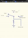
This shouldl be achievable easily through one of those 3 position rockers switches (or 2 normal switches as my above post). As the meanwell needs between 2.8 and 6 volts or an open ciruit to drive it on, the easiest circuit is probably like the one I attached below. You'll need a 2.8 to 6 volt source to make it work. In 1 position, the controller will drive the LDD, with backup to turn the lights off if the controller fails and also when the controller is booting. In the middle position, the pull down resistor should ensure the meanwell pwm is below .8 volts or grounded, and should be off. The third position will drive the pwm input to pull up situation, and should dive the LDD on irrespective of the controller's pwm input.This is exactly why I am programming in 3 presets to my LED controller - I am thinking 1 preset for normal operations; 1 to show off the fluorescence in the corals (mainly royal blue, violet, cyan etc); and 1 for photography purposes (less blue and more white).
At least, that's the theory:). I'm sure there are better or smarter ways to achieve this, probably without the additional voltage source, but I can't think of a simple circuit right now....:( It would somehow entail leaving the pwm input open, with the controller output also open...
Cheers,
arn
Attachments
-
 219.9 KB Views: 42
@arn, I think I mentioned this previously, not sure :confused: I think the easiest way to do this sort of thing is in the software rather than the hardware, although I do realise that you are talking about modding the Typhon which makes things a little more difficult.
This video gives you an idea of what I have done with my controller
In relation to some of your other comments above :
:)
This video gives you an idea of what I have done with my controller
In relation to some of your other comments above :
- LDD's come in a variety of current levels, although the highest is currently 1,000 mA.
- A 1000mA LDD reduced to 70% via a PWM control signal averages out to around 700mA but this is NOT what the LED see's. The LED is switched quickly between 1000mA and 0 mA - if this was hooked up to a LED with a maximum current rating of 700mA you would end of shortening the life of the LED. Irrespective of the amount of dimming via the PWM input you should not use a LDD which exceeds the current rating of the LED's.
- There has been some discussion on ReefCentral regarding what happens to the LED's if the controller is out of action. A power failure would take both out so this scenario is not relevant. I have been running my existing controller 24/7 for 4 years and have not had an issue. That being said, my view is that if the controller fails then I would want my lights to be on. Others have taken the opposing view, which is fine, and there has been a variation to the board developed which does include pulldown resistors.
:)
Agree completely that software is the best way to go:). Unfortunately not all controllers have the ability your's does and dimming through some of them can be a pita!! Circuits such as the ones above make it easy to switch for those who do not have access to such controller, or who wish to be able to use a switch for some other reason (some people have their reasons...:confused:)@arn, I think I mentioned this previously, not sure :confused: I think the easiest way to do this sort of thing is in the software rather than the hardware, although I do realise that you are talking about modding the Typhon which makes things a little more difficult.
Incidentally, I am not modding a typhon as I am using an arduino in my build, however I did note that earlier in this thread the question was asked about manual switching of LEDs through the LDD and I did not see a reply, hence my input above regarding a possible solution if people wanted to go that way.
I am in agreement with everyone that has posted on your thread that your controller is the ultimate way to go. I will be in line to buy you beers if (when) you release it to the community. :worship FWIW I have rewritten much of the jarduino code to work on a 400 x 240 screen as I purchased the screen in anticipation of you build and needed a "quick solution" to try and drive the LED build I am completing.This video gives you an idea of what I have done with my controller
My bad on the availability1500ma LDD (I can't believe the grammar I just wroteIn relation to some of your other comments above :
- LDD's come in a variety of current levels, although the highest is currently 1,000 mA.
- A 1000mA LDD reduced to 70% via a PWM control signal averages out to around 700mA but this is NOT what the LED see's. The LED is switched quickly between 1000mA and 0 mA - if this was hooked up to a LED with a maximum current rating of 700mA you would end of shortening the life of the LED. Irrespective of the amount of dimming via the PWM input you should not use a LDD which exceeds the current rating of the LED's.
- There has been some discussion on ReefCentral regarding what happens to the LED's if the controller is out of action. A power failure would take both out so this scenario is not relevant. I have been running my existing controller 24/7 for 4 years and have not had an issue. That being said, my view is that if the controller fails then I would want my lights to be on. Others have taken the opposing view, which is fine, and there has been a variation to the board developed which does include pulldown resistors.
:)
 ) I mixed up the availability of 1500ma LEDs vs the availability of LDDs. I understand the issue with "overdriving" the LEDS with a LDD that is rated above the LED. I hope no-one thought that was what I was suggesting in fact it was the exact opposite that I would have suggested. It IS possible to use a LDD of a less value (say 500ma) to drive a LED of higher rating (eg 700ma or 1500ma) with the result being that the LEDs will not be as bright at all pwm settings (or straight on or off) as opposed to matching the LDD exactly with the LED. The added benefit of this is a possibly longer life of the LED as they will run cooler.
I'll have a look at the reefcentral site to see what they are talking about
 . I haven't run a controller yet so I do not know what sort of failure rate there is on them. I'm thinking in my scenario I may run some of the lighting circuit with a pull down resistor so that if I do experience a controller failure I have at least some lights on. It will really depend on the strength of the output from the light array I am building as to which way I go (I guess the other alternative is to run lower rated LDDs...) As you said, there are opposing views on this, and both have their merits.:) Indeed, if the controller's reliability is anywhere near the one that you have been running, then the use of a pulldown resistor is a moot point unless you wish to have some form of manual hardware control over the LEDs.
Cheers,
arn.
@arn your reply's are getting longer than mine :D
Part of the discussion above is about what happens when the controller fails to provide the PWM control signal to the LDD's. This could happen if the controller looses power, but the LED's don't or the controller fails to restart for some reason etc. Note - my controller has been running for 4+ years with no problems :)CAN SOME ONE PUT THIS INTO ENGLISH FOR US :)
With the boards that I have obtained the LED's would be on full power in this scenario. Some people think that this is bad as it would have a severe impact on the corals/fish if the lights are left on for an extended period of time. They would prefer the LED's to be turned off, and a variation of the board has been developed to achieve this outcome.
Lets say you are away from the tank for a few days - would you prefer the lights to be on or off during this period??
If they were on all day, every day then I can understand that this might be a problem but probably no worse than being off. But, I have my power supply for the LED's on a seperate timer which turns on 15 minutes before the lights and turns off 15 minutes after the lights and so even if the controller fails the LED's are still on for roughly the same amount of time albeit at full power.
So, my view is that the boards that I have obtained are just what I want and do not need changing....
LDD Type Number of LED's connected to LDD Forward Voltage of each LED - default = 3.5v
Minimum Power Supply Specification
LDD - 1000H 14 3.5 Volts 52
LDD - 1000H 14 3.5 Amps 16.2
LDD - 1000H 14 3.5 Watts 634
LDD - 1000H 14 3.5
LDD - 1000H 14 3.5 Total number of LED's 192
LDD - 1000H 14 3.5
LDD - 1000H 12 3.5
LDD - 1000H 12 3.5
LDD - 1000H 12 3.5
LDD - 1000H 12 3.5
LDD - 1000H 12 3.5
LDD - 1000H 12 3.5
LDD - 700H 6 3.5
LDD - 700H 6 3.5
LDD - 700H 6 3.5
LDD - 700H 6 3.5
LDD - 700H 6 3.5
LDD - 700H 6 3.5
Hi
can you please hook me up with your LDD full kits
according to the chart i think i need 4pcb and 18ldd
im concern about the psu
can i please gimme some of your input and what will be the best way to run the system
my tank size is 6*3*2.5
planning 6 panels of leds and each panel will have 32 leds
thanks
long
Part of the discussion above is about what happens when the controller fails to provide the PWM control signal to the LDD's. This could happen if the controller looses power, but the LED's don't or the controller fails to restart for some reason etc. Note - my controller has been running for 4+ years with no problems :)
With the boards that I have obtained the LED's would be on full power in this scenario. Some people think that this is bad as it would have a severe impact on the corals/fish if the lights are left on for an extended period of time. They would prefer the LED's to be turned off, and a variation of the board has been developed to achieve this outcome.
Lets say you are away from the tank for a few days - would you prefer the lights to be on or off during this period??
If they were on all day, every day then I can understand that this might be a problem but probably no worse than being off. But, I have my power supply for the LED's on a seperate timer which turns on 15 minutes before the lights and turns off 15 minutes after the lights and so even if the controller fails the LED's are still on for roughly the same amount of time albeit at full power.
So, my view is that the boards that I have obtained are just what I want and do not need changing....
ahhh I see I think like this option as would prefere lights on
Latest posts
- Replies
- 0
- Views
- 13
- Replies
- 0
- Views
- 20
- Replies
- 0
- Views
- 13
- Replies
- 0
- Views
- 15
- Replies
- 0
- Views
- 27